Description
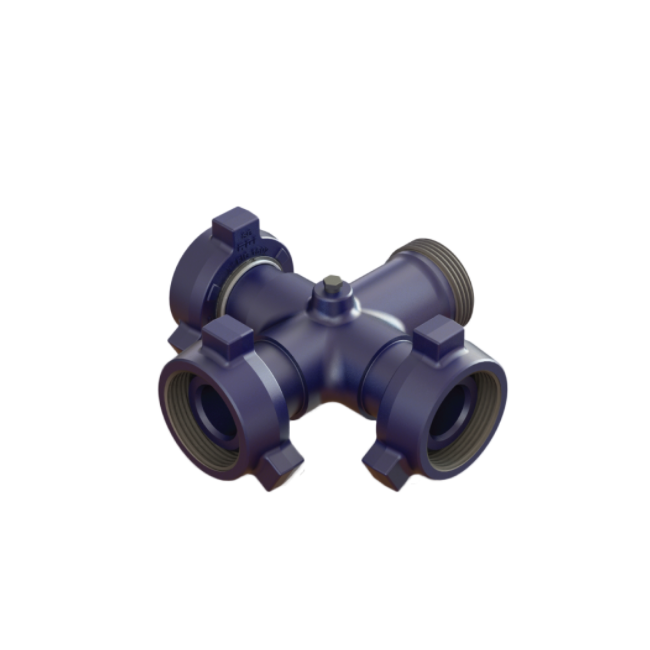
API Standard High Pressure manifold tee / cross tee / integral fittings
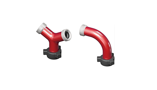
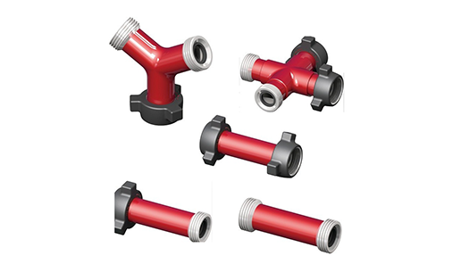
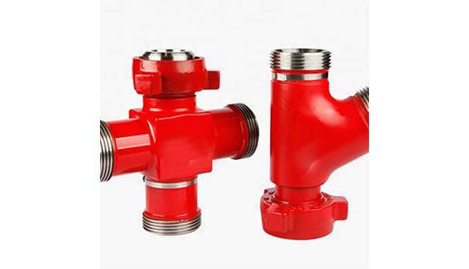
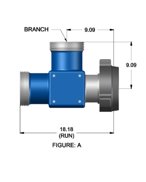
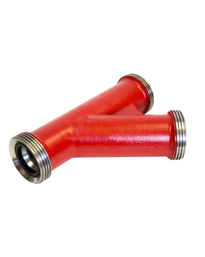
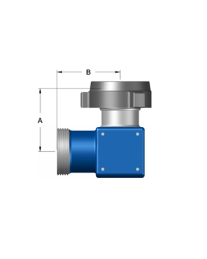
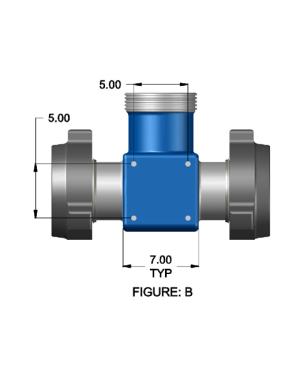
Integral fittings are cementing and fracturing equipment High Pressure Fluid Control Products. Widely used in the acidic operating environment (excluding containing CO2, H2S sour gas operating environment) in the high-pressure discharge line, input line, a temporary flow line, well testing, and other high-voltage transmission lines on pipelines.
There are high-voltage connector specification 2in ~ 4in, rated working pressure 42MPa ~ 105MPa, working temperature -46 ℃ ~ 121 ℃. Integral fittings technical parameters and performance specifications are in line with API 6A.
Its product specification level PLS3, performance levels for the PR2, it can work with SPM’s similar products interchangeable.
1. High pressure integral fittings can connect with all kinds of crushing and cementing equipments at spot;
2. Integral manifold joint includes long sweep elbow, right angle elbow, Tee, Y-tee, manifold Tee, cross tee, manifold cross, integral fittings with specifications of 2’’, 3’’ and cold working pressure 42MPa~105MPa(6000Psi~15000Psi).
Design Features
1. Integral fittings are made by high-strength alloy steel characterized by high pressure bearing and long life span;
2. After heat treatment hardening and tempering, it shows good surface gloss;
3. Thread is made by imported tooling, thus it has good sealing;
4. The terminal end is connected by union, which ensures convenient and fast use.
|
Common Buckle Models for Integral Fittings
|
|||
|
Production name
|
Buckling size
|
Working environment
|
Buckle model
|
|
long sweep elbow
|
2″
|
42Mpa(6000psi)
|
F×M,M×M,F×F,Welding type
|
|
right angle elbow
|
3″
|
70Mpa(10000psi)
|
|
|
Tee
|
105Mpa(15000psi)
|
FMF,FMM,FFM,FMF,MMM,FFF,Welded fitting
|
|
|
Y-tee
|
MFF,Welded fitting
|
||
|
manifold tee
|
MFF,FFF,Welded fitting
|
||
|
cross tee
|
FFFF,FFMF,FFMM,FMMM,FMMF,MMMM,Welded fitting
|
||
|
manifold cross
|
MFFF
|
||
|
integral fitting
|
2″ ×3″
|
Terminal connection type
|
Adapter:F×M,F×F,M×F,B×F,
|
|
2″ ×4″
|
fig602-fig1002
|
M×P,flange fitting×union,Welded fitting
|
|
|
3″ ×4″
|
fig602-fig1502
|
||
|
fig1002-fig1502
|
|||
|
Remark:
1. Each terminal end of Integral fittings can be customized in size (reducing nipple) 2. “F”-threaded joint,“M”-sphere joint,“B”-Internal thread,“P”-male thread 3. How to place an order:cross tee-3″×105Mpa(15000psi) – FFMM |
|||


 Our company has been in the oil & gas drilling equipment industry for over more years, We are here to serve all your drilling equipment needs.
Reviews
There are no reviews yet.